Technology
Introduction of Liquid Nitrogen Generator" EMP Series" and New Product" UMP-40W"
1. Introduction
Liquid nitrogen is commonly used as a cryogenic refrigerant.
Reasons why it is commonly used are that the nitrogen gas that it consists of accounts for 80% of air and so a large quantity of liquid nitrogen can be easily manufactured and obtained, nitrogen gas is inert, and it has a large thermal capacity which means it has a long retention time.
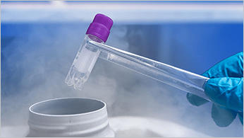
Liquid nitrogen has become essential to our lifestyles. Medical purposes it is used for include shielding for the liquid helium used for MRIs and cold temperature medical and beauty treatments. Physical and chemical applications include shielding for the liquid helium used for NMR spectroscopy and impurity removal in component analyses such as gas chromatography. And, it is used to freeze-preserve sperms and egg cells in the agricultural and livestock industry. In addition, the largest part of the price of liquid nitrogen is the cost of transportation. Liquid nitrogen can be purchased cheaper than milk when a large quantity is purchased at once because the transportation cost can be reduced.
On the other hand, purchasing a small quantity of liquid nitrogen increases the unit price of its transportation cost, which makes the total cost high. There is a significant increase in transportation cost to rural areas that are difficult to access.
To resolve this issue, liquid nitrogen generators have been put on the market to manufacture liquid nitrogen near the locations where it is used and supply it to users who use only small quantities of it.
UCI' liquid nitrogen generators can manufacture liquid nitrogen at over 99% purity from the air only using electricity and water.
UCI has recently started selling the newly manufactured model "UMP-40W" that can produce 40 L of liquid nitrogen per day. This paper presents a report on liquid nitrogen generators along with the introduction of the new model.
2. Outline of liquid nitrogen generators
Table 1 lists UCI' liquid nitrogen generator models.
UCI took the technologies for liquid nitrogen generators which UCI got from Iwatani Industrial Gases Corp., and modified the generators to make them easier to use.
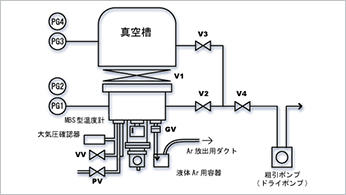
Figure 1 illustrates the process flow in a liquid nitrogen generator.
A liquid nitrogen generator consists of a nitrogen gas generator that separates and extracts nitrogen gas from the air (generation method: pressure swing adsorption
(PSA)) and a main body that liquefies the nitrogen gas.
The main body of the liquid nitrogen generator has a cryocooler for liquefying nitrogen gas, a vacuum heat-insulated vessel to store the liquid nitrogen, a level gauge, safety devices, and a control system in it.
An optional function is available to automatically supply liquid nitrogen to the specified level in a vessel that a customer provides. This function will save time and effort for
customers replenishing their liquid nitrogen supply.
The capacity for manufacturing liquid nitrogen is mainly decided by the cryocooler's refrigeration capacity. By combining PSA, which has an appropriate nitrogen gas feed capacity, with a storage tank of an appropriate capacity, the models listed in Table 1 can handle a wide range of quantities consumed per day.
Table 1 Lineup of the liquid nitrogen generator
| EMP-07 (A/W) | EMP-14 (A/W) | EMP-20W | |
|---|---|---|---|
| LN2 Production Capacity (60Hz/50Hz) | 8L/day / 6L/day | 14L/day / 14L/day | 20L/day / 19L/day |
| LN2 Storage Capacity | 40L | 40L | 80L |
| Dimension (WxDxH) | 600 x 750 x 1628 mm | 600 x 750 x 1688 mm | 930 x 740 x 1661mm |
| Weight | Approx. 220kg | Approx. 235kg | Approx. 340kg |
| Power Supply |
100VAC 1 Phase1.2/1.4kW(50/60Hz) |
200VAC 3 Phase 1.7/2.0kW(50/60Hz) |
200VAC 3 Phase 3.3/4.1kW(50/60Hz) |
| Recommended Breaker Capacity | 20A | 20A | 30A |
| Compressor Cooling System | A: Air W:Water | A: Air W:Water | Water |
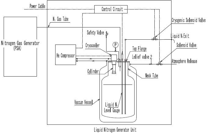
Figure 1 Flow sheet of the liquid nitrogen generator.
3. Elements to be considered in design
Factors that affect the generation rate and influence the concentration of impurities in supplied nitrogen gas (amounts of moisture and Ar gas) are explained below as elements to be considered when liquid nitrogen generators are designed.
3-1. Factors that affect generation rate
Theoretically, the simplest way to calculate generation rate is to total the nitrogen gas' sensible heat (hg (J/g)) from room temperature to 77.3 K and add that to the latent heat required for liquefaction (lv (J/g)). These should then match the cryocooler unit's ideal refrigeration capacity (Q (W)) at 77.3 K. In reality, there are other factors such as heat input from the outside (α (W)) and the vacuum heat-insulated vessel's evaporation loss (β (L/day) and q (W)). Therefore, when such factors are taken into account, the generation rate (A (L/day)) can be expressed with the following formula.
![]()
Where, ρ (g/L) is the density of the liquid nitrogen.
Possible causes of the heat input (α) are 1) radiant heat from the room temperature section via the top flange, and 2) solid heat conduction from the pipes inserted in the liquid phase.
Regarding 1) the radiant heat, when the cryocooler is operating, the temperature of the section above the neck tube of the vessel is always around 77.3 K, so its effect is negligible.
Regarding 2) the heat conduction, the quality of the materials of the pipes and their diameters and thickness were chosen to make the heat conduction sufficiently smaller without impairing their strength.
A cause of the evaporation loss (β) is heat conduction of the neck tube of the vacuum heat-insulated vessel.
β is a characteristic unique to each vessel. Commercially available vessels are purchased, so the actual evaporation loss is measured and only vessels that satisfy the criteria are selected.
q (W) originates in the difference between the temperature of the cryocooler stage and that of the condensing surface (77.3 K). This occurs because when the temperature lowers, the refrigeration capacity decreases as a characteristic of cryocoolers. The causes are listed below.
1) Temperature gradient due to involvement of a liquid nitrogen layer
2) Dependence on the quality of the material of the panel and its thickness depending on the area and shape of the panel
3) Insufficient condensation plane, which occurs in a supercooled state when the condensation plane is extremely small.
3-2. Relationship between the refrigeration capacity and the generation rate
The relationship between the refrigeration capacity of a cryocooler and the generation rate is discussed below.
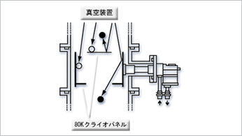
Usually, the refrigeration capacity of a cryocooler is measured in an ideal environment in a heat-insulated vacuum where the cooler is shielded to cut off radiant heat input. However, the cryocooler in the UCI' generator is placed in a space filled with nitrogen gas, so the effective refrigeration capacity is different from that in an ideal environment. For example, if gas in the vessel goes out from the vessel in a low-temperature state before becoming liquid, that means the gas was cooled uselessly, which is a loss of refrigeration capacity. In order to minimize such refrigeration capacity loss and maximize the refrigeration capacity used for liquefaction, a heat-insulating material is put in between the cryocooler and the neck tube to prevent gaseous convection in the neck tube and in the space outside of the cylinder (see Figure 2).
The heat-insulating material is made from plastic foam. The heat conduction of this material is poor and it allows gas to flow.
In the x direction, the insulating material is provided to prevent the neck tube's temperature gradient from affecting the cylinder's temperature gradient. This causes a temperature gradient on the inner surface of the heat-insulating material along the cryocooler cylinder, and that makes the temperature gradient of the nitrogen gas in the horizontal direction smaller.
Consequently, the nitrogen gas cooled by the cryocooler moves downward because it becomes heavier when the density increases as the temperature lowers. The temperature gradient in the y direction can cool without impairing the cylinder's cooling capacity. This makes it possible to cool the nitrogen gas' sensible heat by using the cylinder's temperature gradient and neck tube in addition to the capacity of the cooling end, which makes liquefaction of the generation rate shown with formula (1) more efficient.
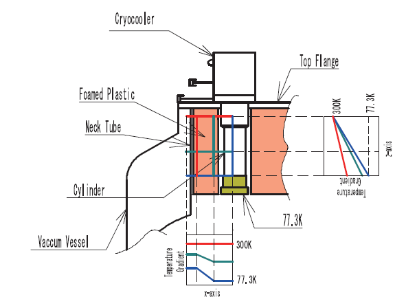
Figure 2 Temperature gradient caused by thermal insulation
3-3. Dew point of the supplied gas
Currently, the dew point of gas supplied by PSA is standardized at -60℃ or lower and generators are manufactured based on this specification.
At 77.3 K, of course water is ice. When the cryocooler is operating, ice forms on the section of the cylinder where the temperature is around -60℃. When the liquid is taken out or the vessel becomes full, the cryocooler stops operating. At this time, the ice partially melts and moves downward. As the cryocooler repeatedly starts up and stops, ice builds up on the bottom of the vessel. If the dew point is too high, ice does not move downward but forms over all of the heat-insulating material and grows. These chunks of ice may cause the level gauge to malfunction, make it impossible to remove the cryocooler during maintenance, or cause other problems.
3-4. Ar gas in the air
The air contains approximately 1% Ar gas. This Ar gas gets into the vacuum heat-insulated vessel without being removed by the PSA. The boiling point of Ar gas is 87.3 K and the triple point is 83.8 K. At 77.3 K, solid Ar forms a layer on the surface of the cooling end and that may deteriorate the heat exchange efficiency between the nitrogen gas and the cooling surface, which may result in reduction of the generation rate. However, Ar completely evaporates when the cryocooler stops operating, such as when the liquid nitrogen is taken out, so the generation rate goes back to normal.
4. Machine components
4-1. Nitrogen gas generator (PSA)
A PSA consists of an air compressor, buffer tank, control unit, and two adsorption columns. Air compressed to approximately 0.8 MPa by the compressor is cooled by the air-cooled heat exchanger. Moisture is removed and then the air is put into one adsorption column. The activated carbon in the adsorbent adsorbs oxygen gas, carbon dioxide gas, moisture, and other substances from the compressed air passing through the adsorbent, which makes the nitrogen gas highly pure. This pure nitrogen gas is stored in the buffer tank from the outlet side of the adsorption column (during these steps, the other adsorption column is in standby).
When adsorption becomes saturated, the adsorption column is switched and the other adsorption column starts adsorption. At the same time, the adsorption column that has been adsorbing oxygen gas and other substances is opened to atmospheric pressure and the oxygen gas and other substances are easily desorbed in preparation for the next adsorption. Switching back and forth between the two columns and using the buffer tank allows high purity nitrogen gas to be stably supplied in a uniform flow.
4-2. Cryocooler unit
The Japanese High Pressure Gas Safety Act applies to cryocooler units used in Japan (discussed later). Therefore, the cryocooler unit parts that come in contact with nitrogen gas must be manufactured in accordance with the act as high pressure gas receivers. As welded pressure receivers cannot satisfy the welded structure specified in the act, the "EMP series" pressure receivers are seamlessly processed.
4-3. Storage vessel
Storage vessels that UCI purchases conform to the Japanese High Pressure Gas Safety Act.
The heat-insulating vacuum structure is the same as that of commercially available SUS vessels, but cryocoolers, level gauges, etc. need to be installed into them, so the diameter of the openings of the top flanges is larger.
4-4. Level gauge
Capacitance type level gauges are used. A level gauge has an electrode at the center with a tubular ground electrode surrounding it. It can measure the liquid level by measuring changes in the capacitance caused by differences in the permittivity between liquid nitrogen and nitrogen gas. It can continuously measure the liquid level thanks to the voltage output. However, the presence of even a little ice or foreign matter makes accurate measurement impossible, so attention needs to be paid to keep anything from getting in, especially ice.
5. Compliance to the Japanese High Pressure Gas Safety Act
UCI' liquid nitrogen generators are handled as condensers in Japan under instruction by the Japanese Ministry of Economy, Trade and Industry. When handled as condensers, generators are divided into general high pressure gas equipment and designated equipment in accordance with the formula below.
Design pressure (MPa) × vessel capacity (m3)=0.004
When the value for a generator calculated by the formula exceeds 0.004, it is handled as designated equipment and subject to material tests of its components, welding procedure checks, welding tests, and liquid penetrant tests. These tests also apply to cryocooler cylinders, which makes it practically impossible to manufacture cryocoolers.
Therefore, UCI' liquid nitrogen generators are designed with design pressures with which the values calculated using the above formula are 0.004 or less to allow them to be handled as general high pressure gas equipment. In addition, generators have safety valves to prevent them from being considered designated equipment.
On the administrative side, applications must be submitted to each prefectural government, so naturally the installation and test conditions for each component slightly vary depending on how the local government interprets the act.
6. The" UMP-40W"
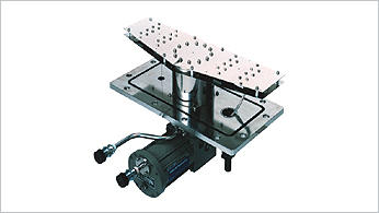
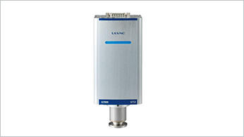
Last but not least, the new" UMP-40W" that was put on the market recently is described below. Figure 3 shows its appearance.
Cryocoolers, compressors, control methods, and other UCI' products and technologies have been incorporated into the liquid nitrogen generator "UMP-40W" manufactured based on the" EMP series" (products UCI got from Iwatani Industrial Gases Corp.). The "UMP-40W"'s liquefaction capacity is 40 L per day. This is among the best for liquid nitrogen generators and is high enough to compete with the generators of overseas manufacturers.
The refrigeration capacity of the high-power Gifford- McMahon type cryocoolers (RMS150T) is 165 W/77 K. Note that the cylinder sections (pressure receivers) have been welded meaning that this model does not conform to the Japanese High Pressure Gas Safety Act, so this model is sold only overseas. This is one of the main differences with the" EMP series".
Although this model cannot be sold in Japan, areas (mainly Southeast Asia) where it is difficult to obtain liquid nitrogen are potential markets.
6-1. Generation rate
The sensible heat of 1 kg of nitrogen (h300K-77K) and its latent heat (lv) are shown below1).
h300K-77K =233.8 J/kg
lv =199.1 J/kg
The total of the sensible heat of 1 kg of nitrogen and its latent heat (Q) is calculated using the formula below.
h300K-77K+lv=432.9 J/kg
The refrigeration capacity of the cryocooler is 165 W (J/sec). When the density of liquid nitrogen (ρ =804.2 g/L) is used, the ideal generation rate without considering heat input and evaporation from the vessel is calculated using the following formula.
![]()
The specification (generation rate (A)=40 (L/day)) is satisfied according to the calculation.
Figure 4 shows actually measured generation rate values for the new" UMP-40W".
Figure 4 shows that the measured generation rates sufficiently exceed 40 L/day. This is because the sensible heat is able to be cooled effectively thanks to the temperature gradients of the cylinder and heat-insulating material.
The generation rate per day was converted from the difference calculated by deducting the gas flow rate at the outlet of the vessel from that at the inlet.
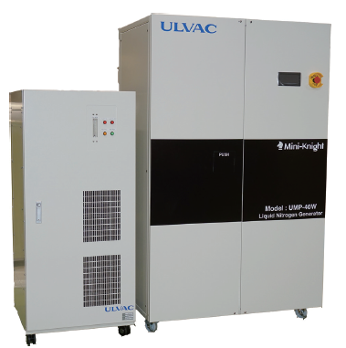
Figure 3 Overview of the "UMP-40W" and Nitrogen gas generator (GN-30i)
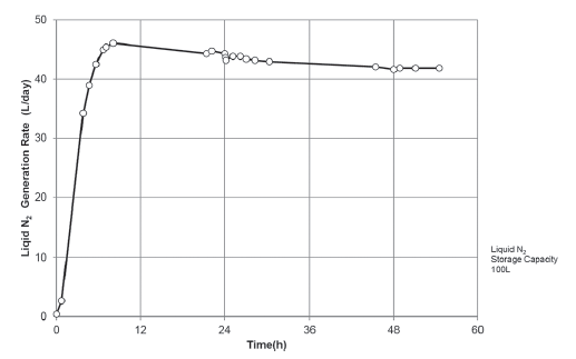
Figure 4 Liquid N2 Generation rate of the "UMP-40W".
6-2. Relationship between the liquid level and the generation rate
As Figure 4 shows, as the liquid level becomes higher (as time passes), the generation rate gradually decreases. This is possibly because of the influence of Ar gas. Another possible cause is that the length of the cryocooler cylinder is shorter than that of the "EMP series" and the temperature gradient may have an effect. Either way, the authors will continue to manufacture liquid nitrogen generators and verify this point.
7. Conclusion
There is high latent demand for liquid nitrogen generators in areas (mainly in Asia) where it is difficult to obtain liquid nitrogen and as their economies grow, the number of generators sold could shoot up.
The liquid nitrogen produced by the "UMP-40W" needs to be taken out manually. UCI is planning to develop an automatic type in the future (e.g., precooling of superconducting magnets).
We have high hopes for future market expansion.
Reference
1) Cryogenic Association of Japan : Choudendou・ Teionkougaku Handbook.
Technology
-
Pioneering Hydrogen Leak Detection for a Sustainable Future: ULVAC's HELIOT 900
-

Reliable and Efficient Leak Detection Solutions for Battery Manufacturers: ULVAC's HELIOT 900
-

Introduction of Liquid Nitrogen Generator" EMP Series" and New Product" UMP-40W"
-
"LS Series" Dry Vacuum Pumps with High Pumping Speed and Low Power Consumption
-
Applications of Process gas monitor.
-
Launch of Cryogenic trap using a helium refrigerator to replace CFC substitute cold trap
-
Rapid low-temperature regeneration ... Reduction of regeneration time.
-
Applications and examples of effective use of Super Traps
-
Liquid Nitrogen Generator in diverse fields
-
Vacuum Gauge ST2 Technical report
-
Liquid Nitrogen Generators | Technical Report
-
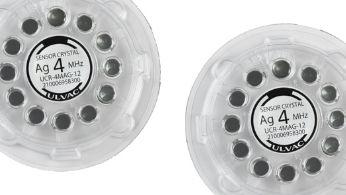
Development of a quartz crystal disc with a resonance frequency of 4 MHz
-

HELIOT900 | Technical report
-
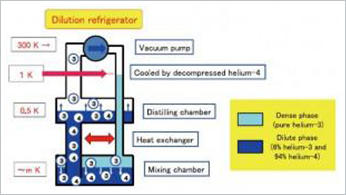
Cryogen Free Dilution Refrigerator using 4K-Cryocooler
Solution
- Big Science
- Lifestyle
- Technology
- Medical Field