Technology
"LS Series" Dry Vacuum Pumps with High Pumping Speed and Low Power Consumption
1. Introduction
When vacuum equipment is required in order to increase microfabrication density and improve productivity, it is increasingly common to turn to dry vacuum pumps . As a result of environmental concerns, customers are becoming more and more interested in reducing power consumption . At the same time, customers want to reduce pumping time and increase productivity . However, typical dry vacuum pumps that feature low power consumption tend to require long pumping times because of their low pumping speed near atmospheric pressure . To solve this problem, we have developed and are now marketing a series of dry vacuum pumps called the "LS series ." Pumps in this series (see Figure 1) combine high pumping speed with low power con- sumption . In this article, we introduce the characteristics of the dry vacuum pumps in the LS series .
2. Product specifications
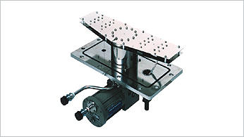
Table 1 shows the product specifications of the dry vacuum pumps in the LS series . We offer four models with different maximum pumping speeds: the LS120A standalone dry vacuum pump (Figure 2) and the LS300A, LS600A, and LS1200A dry vacuum pumps combined with mechani- cal booster pumps (MBPs) (Figure 3) . With each of these models, we offer the low-power-consumption C Type that features built-in ECO-SHOCK technology for application in clean processes (such as air and N2 pumping), and the L Type that features surface treatment and purge functions for application in light-duty processes (such as evacuation of water vapor and volatile chemicals) . Applications for the C Type include sputtering, evaporation, bonding, load lock chamber pumping, and use as an auxiliary turbomolecular pump . Applications for the L Type include vacuum drying, vacuum freeze drying, ashing, and general industrial use . All models in the LS series allow continuous operation across the full range of inlet pressures .Outline drawings of the pumps are shown in Figures 4 and 5 . Table 2 shows the dimensions indicated in each of the pump outline drawings .
3. Need for high pumping speed and low power consumption1)
In vacuum processes in manufacturing fields such as semiconductor devices and flat panel displays (FPDs), pro- cesses such as chemical vapor deposition (CVD), etching, and sputtering are performed . In addition to the process chamber used for CVD, etching, sputtering, and other pro- cesses, vacuum equipment used in mass production also has a load lock chamber that pumps the substrate down from atmospheric pressure to prevent the vacuum process chamber from exposure to the atmosphere due to substrate loading or unloading . The vacuum pump equipment in the load lock chamber includes a dry vacuum pump and an MBP, and typically evacuates the chamber to a pressure that is lower than the maximum inlet pressure of the turbomo- lecular pump when the next chamber valve is opened .
To shorten cycle time and improve efficiency in mass pro- duction, it is desirable to reduce the time required to evacu- ate the load lock chamber to the predetermined pressure . To shorten the pumping time of the load lock chamber, the pumping speed of the dry vacuum pump near atmospheric pressure becomes an important factor . This is because when the pressure in the load lock chamber is high, such as several thousand Pa or greater, the boost provided by the MBP will be small, so any change in pumping time will be dependent on the pumping speed of the dry vacuum pump
3-1. Pumping speed of the dry vacuum pump near atmospheric pressure
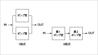
In a typical volume transfer-type vacuum pump, spaceis created between a moving body (such as a rotor) and a fixed body (such as a stator) in order to evacuate the gas. If the target ultimate pressure cannot be achieved using a single stage, a multiple-stage configuration is used . Unlike an oil-sealed rotary vacuum pump with an exhaust valve, the pressure on the exhaust side of a dry vacuum pump is always at atmospheric pressure . Accordingly, to maintain the vacuum at the inlet side, gas flowing to the pump cham- ber must be pushed back during the compression stroke . The subsequent stage that receives the backflow from atmo- spheric pressure performs work that greatly impacts the overall power required to push back the gas . In the power-saving dry vacuum pump, the volume of the pump chamber in the subsequent stage is reduced to lessen the gas com- pression work required of the subsequent stage . However, when the inlet pressure is higher than several thousand Pa, pumping speed is lower because of the smaller volume of the subsequent stage . In the case of a multistage configura- tion, although it is possible to reduce the pumping speed by evacuating the gas from the middle stage, the pumping speed near atmospheric pressure is low when compared with a configuration that has a subsequent stage with a larger volume . There is a great demand for shortening the time required to pump to the predetermined pressure in the load lock chamber . Reducing the volume of the subsequent stage is disadvantageous because the pumping speed near atmospheric pressure greatly impacts pumping time .
3-2. ECO-SHOCK
The ECO-SHOCK® dry vacuum pump Power-Saving Attachment (hereinafter referred to as "PSA") enables a maximum 80% reduction in the power consumption of dry vacuum pumps used in the evacuation of inert gases such as air, nitrogen, or argon from load lock chambers, etc . Reduc- ing power consumption also has the effect of suppressing heat generation by the dry vacuum pump, and so reductions in power consumption by air conditioners and other equip- ment can also be expected .
The PSA is installed as a check valve and backing vacuum pump in parallel at the exhaust port of the main pump, which is the dry vacuum pump in which reduced power consump- tion is desired . When the inlet gas flow of the main pump is low, the PSA lowers the pressure inside the main pump, reducing the gas compression work of the main pump and thereby reducing power consumption . We have acquired patents2)-7) for backing vacuum pump selection criteria that can achieve efficient power savings for vacuum pump sys- tems in which a backing vacuum pump is used with a main pump and the PSA . A patent also has been acquired for a check valve mechanism to facilitate installation .
3-3. Combining high pumping speed and low power consumption
The C Type has built-in ECO-SHOCK technology,enabling both high pumping speed and low power consump- tion . In addition, because the main pump is not limited by outlet pressure, continuous operation across the full range of inlet pressures is possible .
4. Comparison of LS120A and the conventional model LR90
To demonstrate LS120A features other than high-speed pumping and low energy consumption, let us compare it with the LR90, another dry vacuum pump marketed by ULVAC that has a similar maximum pumping speed .
4-1. Low noise
The silencer, which is connected externally to the main body of the LR/HR series as optional equipment, is built-in to the pump package as standard equipment . The noise level at ultimate pressure is 66 dB(A) on the LR90, but is reduced to no more than 61 dB(A) on the LS120A .
4-2. Low operating cost
Operation of the LR90 requires 5 L/min of N2 shaft seal- ing gas and at least 5 L/min of cooling water flow . On the LS120A, we have developed a compact mechanism that seals the oil from the gear chamber to the pump chamber, eliminating the need for shaft sealing gas and reducing the cooling water flow to 2 L/min . These developments contrib- ute to reducing the operating cost of utility power for pump- ing operations .
4-3. External dimensions
The LS120A requires only half of the floor space of the LR90 . In addition, from an environmental perspective, the LS120A has 40% fewer parts and 40% less mass than the LR90 . Also, inlet ports are provided horizontally on the front surface (KF50) and vertically on the top surface (VG50) . This enables easy replacement of older models and of oil- sealed rotary vacuum pumps .
The external dimensions of the LS600A and LS1200A are the same, as the dimensions of the older LR600 and LR1200 models were also the same . As compared with the older LR600 and LR1200 models, the LS600A and LS1200A require only 44% of the floor space and 30% of the volume .
4-4. Motors developed by ULVAC
The motors installed in the LS series were developed by ULVAC . Because of this, we were able to use a canned DC brushless motor with a configuration that is suitable for dry vacuum pumps and MBP design . To achieve power savings, we selected for the motor rotor an IPM configuration with powerful magnets that are highly efficient at high rpm . In addition, use of a fluorine resin coating has made the mag- nets more resistant to corrosion .
5. Long-term reliability and high durability
To ensure stable operation and high durability, we per- formed various reliability tests from the early stages of development .
5-1. Reliability testing
With high-speed pumping as a central feature, we envi- sioned the possibility of load lock chamber pumping, and confirmed that there were no problems after pumping in a 0 .1-m3 test container for more than two years, with repeated atmosphere and vacuum cycles . We also confirmed reliabil- ity through continuous operation and repeated starts and stops at low temperature atmosphere and high temperature atmosphere at the ultimate operation and maximum load . We also acquired cTUVus certification and CE marking, achieving an internationally competitive product .
5-2. Water vapor pumping
The LS series' L Type enables evacuation pumping, such as of water vapor . Using a purge gas enables exhaust of 1 .5 kg/h of water vapor . For water vapor pumping with the LS120A, we performed a durability test with continuous intake of water vapor at 1 .5 kg/h, and we confirmed that there were no problems such as pump breakdowns .
5-3. Motor control system development
To reduce the size of the LS series, we developed a new inverter that controls the DC brushless motor . In load lock chamber pumping and other applications, an MBP produces sudden load fluctuations and large temperature changes . Conventional inverters are large because they include numerous parts needed for controlling these variables . To reduce the external dimensions, we had to reduce the size of the inverter that controls the motor . The software for the new inverter is optimized to allow control of the motor with the minimum configuration . Additionally, we conducted various reliability tests that involved use of the motor under all conditions and confirmed that the unit could be operated stably .
6. Conclusion
We have developed a series of dry vacuum pumps called the "LS series" that combines high pumping speed and low power consumption . ULVAC will continue to develop prod- ucts that meet our customers' needs as we contribute to the ongoing development of industries that rely on vacuum technology .
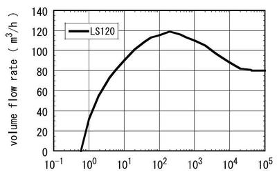
Figure 2

Figure 3
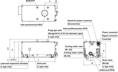
Figure 4
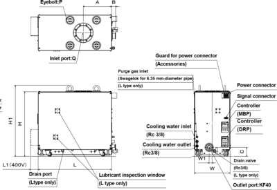
Figure 5

Table 1
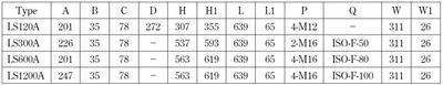
Table 2
References
- T . Tanaka and T .Suzuki: J . Vac . Soc . Jpn ., 58 (2015) 239 .
- Japan patent JP3906973B
- Japan patent JP3982673B
- Japan patent JP3992176B
- Japan patent JP4045362B
- Japan patent JP4180265B
- Japan patent JP4365059B
Technology
-

Pioneering Hydrogen Leak Detection for a Sustainable Future: ULVAC's HELIOT 900
-

Reliable and Efficient Leak Detection Solutions for Battery Manufacturers: ULVAC's HELIOT 900
-
Introduction of Liquid Nitrogen Generator" EMP Series" and New Product" UMP-40W"
-
"LS Series" Dry Vacuum Pumps with High Pumping Speed and Low Power Consumption
-
Applications of Process gas monitor.
-
Launch of Cryogenic trap using a helium refrigerator to replace CFC substitute cold trap
-
Rapid low-temperature regeneration ... Reduction of regeneration time.
-
Applications and examples of effective use of Super Traps
-
Liquid Nitrogen Generator in diverse fields
-
Vacuum Gauge ST2 Technical report
-

Liquid Nitrogen Generators | Technical Report
-
Development of a quartz crystal disc with a resonance frequency of 4 MHz
-

HELIOT900 | Technical report
-
Cryogen Free Dilution Refrigerator using 4K-Cryocooler
Solution
- Big Science
- Lifestyle
- Technology
- Medical Field