Technology
HELIOT900 | Technical report
Leak Detector "HELIOT 900 Series"

1.Introduction
ULVAC first launced the "DLMS" helium leak detector(HLD), on the market in 1967. Then in 1995, ULVAC started selling the "HELIOT 300 series"1) that made it possible to perform large leak and fine leak tests fully automatically for the first time in the world using our original" select free" technology for the vacuum system. Almost 20 years have passed since then.
(※ This article was released in "Technical Journal No.79 published in June, 2015")
Ever since the launch of the "HELIOT 300 series", we have developed several series of HLD for various applications, such as the "HELIOT 100 series"2) of compact and light-weight HLDs for customers who had not used HLDs before, the "HELIOT ZERO"3) HLDs exclusively used for automatic helium leak test systems and the "HELIOT 700 series"4) of general-purpose HLDs.
The market for HLD has expanded from the vacuum, automobile, refrigeration, and nuclear power industries to the food and medical packaging industry.The method of use is also diversifying. In this market environment, we will introduce "HELIOT 900 Series"which aims to improve the basic performance and ease of use of measuring leaks faster and more quickly.
Three features of leak detector HELIOT900
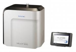
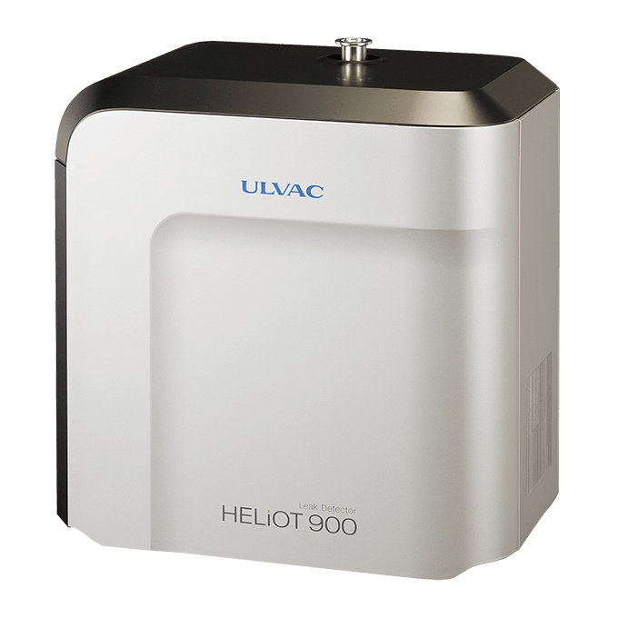
Figure 1 Appearance of a portable type.
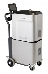
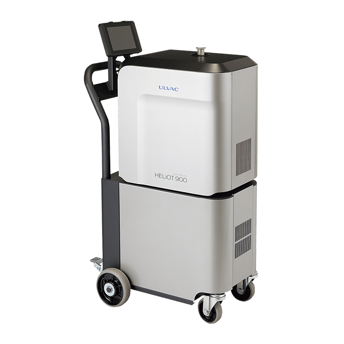
Figure 2 Appearance of a mobile type.
2.Lineup
Figures 1 and 2 illustrate the appearance of the "HELIOT 900 series". Table 1 lists the specifications. Two types of pumps are available just like the "HELIOT 700 series": oil rotary pumps (W1 model: 30 L/min, W2: 135 L/min) and dry scroll pumps (D2 model: 90 L/min, D3: 250 L/min). A new D4 model dry scroll pump (pumping speed: 500 L/min) was just added for semiconductor and FPD manufacturing equipment. The W2, D3, and D4 models which have faster pumping speeds come with a mobile cart as standard equipment.
Connecting an optional sniffer unit allows the user to test DUTs by the snif fer method. This series was designed to make it possible to use different two methods -the vacuum method and the sniffer method-in a single unit.
3.Product features
3.1 Vacuum systems and analyzer tubes
The pumping speed of HLD test port needs to be increased in order to quickly start helium leak tests and to detect leaks in vacuum equipment and automatic leak testers with high sensitivity. However, when the pumping speed of turbo molecular pumps is increased, the amount of helium that reaches the analyzer tubes is reduced, which lowers the sensitivity.
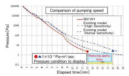
Figure 3 Pumping curves compared to the existing models.
In the "HELIOT 900 series", the pumping speed of the gas inlet ports of the turbo molecular pumps and the conductance of test valves were increased to achieve a pumping speed of 5 L/s (ultra flow). The improvement in the ability to detect micro currents (mentioned later) made it possible to detect leaks with high sensitivity. Figure 3 shows that the time to reach the pressure required to display a background level of 1×10-11 Pa・m3/sec for a DUT with a volume of 30 L was reduced by more than five minutes compared to the existing models.
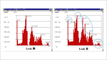
In addition, leaks were artificially developed in a chamber and an HLD was connected to test the DUT while discharging gas with a vacuum pump in the same way as when performing a leak test on vacuum equipment. The result was that leaks one-fifth (1/5) as large as those able to be detect by existing models were able to be detected.
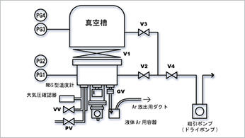
Figure 4 illustrates the vacuum system of the" HELIOT 900 series". This model is equipped with the same" selectfree" vacuum system as that used on the existing models, but the "HELIOT 900" has no function for switching between standard and high sensitive modes. Instead, the "HELIOT 900 series" has three flow modes: Gross flow (connecting pressure: 1,200 Pa), Fine flow (100 Pa), and Ultra flow (2 Pa) to measure fine leaks in addition to large leaks.
The amount of flow during startup was modified and thus the startup time is no more than five minutes including calibration operations and no more than two minutes without calibration.
The vent line has been changed to between the calibrated leak valve and calibrated leak, which prevents increase in the background during continuous operation. Moreover, the newly added D4 model is equipped with a roughing valve which can further reduce the time it takes to pump gas from a DUT.
The components used have also been changed. The Pirani vacuum gauge for monitoring pressure uses the newly developed "SPU"5), which sends the pressure signal to the main board by digital communication. The fore pump of the W1 model is a "GHD-031" made by ULVAC KIKO, Inc. And its magnetic coupling structure allows no oil to leak from the shaft seal, which extends the service life. In addition, an oil mist trap is provided as a standard accessory.
An electrode has been installed onto the analyzer tube to prevent secondary electrons that are produced when the inside of the analyzer tube is dirty or the pressure is high from hitting the ion collector, allowing for more reliable measurement.
Moreover, a hydrogen measurement mode, in which hydrogen can be used as the tracer gas like the existing models, is also provided.

Figure 4 Vacuum system diagrams.
3.2 Micro current detection circuits
Micro ion currents must be accurately measured in order to measure smaller leaks, so micro current detection circuits are important elements that determine the performance of HLDs as is the case with ionization gauges5) and residual gas analyzers6).
In the development of this line, microprocessors were installed onto the micro current detection circuit boards. These microcomputers process most of the operations that are directly related to signal measurement such as sampling, filtering, switching ranges, and calculating output values, without relying on the main boards. The transmission method for sending data to the main boards has been changed from analog voltage to digital communication.
The per formance of operational amplifiers and analog-to-digital converters has been significantly improved compared to the existing models. The output from operational amplifiers is directly converted to digital signals from analog, which allows the signals to be received with a high signal to noise ratio and fine leaks with a minimum detectable leak rate of 5× 10-13 Pa・m3/sec to be detected.
In addition, the response speed was increased while noise was reduced relative to the leak rate by setting the number of moving average filtering based on the current values to be measured. The series has three filtering modes: FAST, NORMAL, and SLOW, so that the filtering mode can be selected based on the application.
In addition, circuits have been simplified, which reduced the number of components; two printed wiring boards are used on the existing models, but only one board is used on this series, so the cost and size was reduced.
3.3 Electric systems and software
The "HELIOT 900 series" uses industrial 7-inch tablets with the Android OS as displays and they can be used as wired or wireless remote controllers. The orientation and angle of the stands that come with the HLDs can be freely changed, so the tablets can be used by standing them up, hanging them, or as remote controllers.
As a result, when performing leak tests with vacuum equipment or by the sniffer method, the controllers used for display and operations can be moved away from the main units without being restricted by layout and cable length for improved user convenience.
The designs of the screens displayed on the tablets are simple and easy to understand. Measurement values can be visually understood with graphs, meters, and values displayed on test screens by setting set points to change the color of the graphs and values displayed.
In addition, the range and measurement time can be changed by pinching in and out of the graph sections (Figure 5).
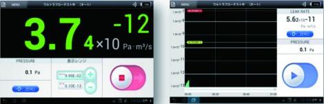
Figure 5 Software screens.
Seven languages are available as before; Japanese, English, Korean, Simplified Chinese, Traditional Chinese, German, and Spanish. The main four new functions are listed below.
①Calibration of sniffer flow rate with built-in calibrated leaks
The flow rate is displayed by calibrating the sensitivity with the calibrated leaks built into the HELIOT units, so an external calibrated leak is not required for the sniffer.
In addition, the method can be switched between the vacuum method and sniffer method after the startup of the detectors, so if leaks are found by the bell jar method, the leak locations of the DUT can be detected without restarting the detectors.
②Vent setting
The posttest vent control method has been redesigned. The available settings include automatic, manual, and disable.
Automatic: The gas will be discharged upon completion of tests.
Manual: The gas will not be discharged upon completion of tests. The test start/finish button on the test screen changes to the vent button. The gas can be discharged at any time.
Disable: The gas will not be discharged at all.
In addition, a new function was added to set the amount of time for which the gas is discharged. This function stops the discharge after the set time has passed. This function is useful when connecting N2 and other gases to the vent lines to discharge the gas and purge air for a certain period of time.
③Data logging function
Optional communications software exclusively for PCs used to be required in order to save the leak rate and other measurement data.
With the "HELIOT 900 series", all the measurement data from start to finish is saved in one CSV format file to the micro SDs that come with the displays. The saved data includes the date, leak rate, and pressure values of the internal Pirani vacuum gauges. This allows users to manage data more easily.
④Cycle tests
The cycle test function has been improved to make it easier to use. This function allows tests by the spray, hood, bell jar, and immersion methods to be automatically performed without using external PLCs.
The hood method procedures are as shown below;
(1)Start vacuuming (pressure judgment)
(2)Start detecting helium (background monitoring)
(3)Start spraying helium (pass/fail judgment)
These operations are automatically controlled. Various times, criteria, and other items can be easily set on the setting screens.
Test screens exclusively for cycle tests have been provided, so the current test processes can be checked and if an error occurs, the test process with the error can be identified.
The connection of external input/output signals is designed to be compatible with the "HELIOT 700 series" excluding the RS232C connectors. In addition, compatibility with leak test systems that were manufactured for the former "HELIOT 300 series" can be maintained by using signal convertors (optional). This design makes replacing the HLD easy.
The "HELIOT 900 series" also inherits a function in which, when helium mixture gas is used, the coefficient is calculated based on the concentration values and after the user inputs the coefficient, the value converted to pure (100%) helium gas is displayed.
3.4 Sniffer units
The "HELIOT 900 series" has two types of sniffer units as shown below (Figure 6).
Unit A: Probe type with a capillary tube installed at the tip
Unit B: A booster pump unit with a small built-in pump installed onto the main unit's test port along with a micro separator
The following points were taken into account when these sniffer units were developed.
①Durability
Every leak test site is different. In order to design a durable sniffer unit, many potential problems need to be considered. For example, measures against clogging of capillary tubes due to foreign matter taken in from near the DUTs and malfunctioning of the equipment due to foreign matter that has gotten into the components of the main units (turbo molecular pumps and seals of various test valves) as well as physical damage to the sniffer
probes caused by mishandling.
For the "HELIOT 900's" sniffer probes, sintered metal elements are used at the beginning of the capillary tubes, which are key components for taking in the test gas, in order to protect the capillar y tubes by physically eliminating the risk of foreign matter larger than the inner diameter of the capillary tubes from being taken in. Also, the elements are fixed to the inside of the probes, which reduces the risk of the elements coming off.
In addition, the material of the handles has been changed from plastic to metal, so the probes are better able to endure falls during leak tests.
2) Response
The capillary tubes are installed at the tips of probes, which means they are as close to the sampling targets as possible, which improves the response by 10 to 20% compared to the existing models (Unit A).
In addition, the ultimate pressure of the booster pumps used for Unit B is lower and the flow characteristics are superior compared to the existing models.
3) Other
The weights of the sniffer probes and hoses have been reduced, so they are easier to handle. Once the booster pump units are connected to the main units' connectors, they will automatically start operating and the main units will start up in leak test mode with the booster pump units recognized.
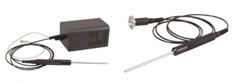
Figure 6 Appearance of a sniffer unit.
3.5 Cases and mobile carts
The standard design of the Components Division was adopted and the weight of the W1 type was reduced by 10 kg compared to the existing models. Users used to have to prepare vent por t joints, but now they are provided on the connector panels. The air-cooling fans have filters to prevent fine dust and dirt from getting inside. In addition, the ability to cool the inside has been enhanced to ensure that the units operate at maximum performance and remain reliable in Southeast Asia and other areas where the temperature is rather high.
The mobile carts have large casters, spaces that users can step on to raise the front wheels when going over steps between floors of different heights, foot brakes, and panel covers without projections or depressions, all of which make it easy to move the detectors. The carts also have spaces for storing the tablets before moving the detectors.
3.6 Maintenance
HLDs use turbo molecular and fore pumps. It is necessary to periodically maintain those pumps and other parts, replace consumable goods, and recalibrate the calibrated leaks. The outer panels need to be removed in such cases and the panels of the "HELIOT 900 series" can be easily removed without using tools. Ion sources are replaceable units as before. The Pirani vacuum gauge heads and calibrated leaks are provided in easy-to-reach locations.
The hose-shaped oil drain ports of W1 model rotary pumps make it easy to change the oil (Figure 7).
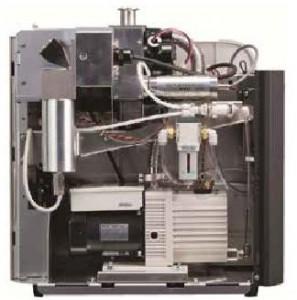
Figure 7 Photograph of the inside of a portable type.
In addition, there are videos on the tablets that show how to maintain the units and replace consumable goods, so users can feel confident even when per forming maintenance or replacement for the first time. Users can set how long maintenance guide screens are displayed.
4.Conclusion
This paper is a report on the development of the "HELIOT 900 series" into which valuable customer requests and opinions have been incorporated. The environment surrounding leak tests using helium has been significantly changing for the past several years7).
Regarding Japanese standards, Japan Industrial Standard (JIS) Z 2330:1992 was entitled "Standard recommended guide for the selection of helium leak testing" and only covered leak tests using helium gas. However, the new JIS Z 2330:2012 standard is entitled "Non-destructive testing-Selection of leak testing methods" covering all leak tests.
With regard to certification of skills, the Japanese Society for Non-Destructive Inspection started certifying technicians' skills in 2012 through a testing process. A factor behind this certification is that the accuracy of leak test results is significantly influenced by the skill levels of non-destructive inspection technicians.
Thus, their skill levels need to be maintained at a certain level.
Helium gas used for leak tests is a ver y valuable resource since the atmosphere contains only a small amount of helium gas and the gas is produced in only limited areas. Therefore, it is necessary to use less helium gas and conserve it in the future.
Given such circumstances, we will continue improving and refining the basic performance and ease of use, improving the calibration technology, proposing optimum test methods and ways to reduce the amount of helium gas used, and we will make it possible to measure finer leaks more quickly and more accurately.
(※ This article was released in "Technical Journal No.79 published in June, 2015")
Three features of leak detector HELIOT900
References
1) E. Ochiai, A. Umezawa: Japanese published examined application No. Hei 8-15708.
2) E. Ochiai: ULVAC TECHNICAL JOURNAL No.50 (1999) 19.
3) T. Maehira: ULVAC TECHNICAL JOURNAL No.74 (2011) 25.
4) ULVAC, Inc.: J. Vac. Soc. Jpn 54 (2011) 64.
5) T. Nakajima, T. Miyashita, Y. Nagata, M. Fukuhara, Y. Uchida, Y. Ohashi and T. Nishimaki: ULVAC TECHNICAL JOURNAL 76 (2012) 8.
6) T. Nakajima, R. Tanaka, T. Yuri, Y. Kurokawa, H. Aoyagi and N. Takahashi: ULVAC TECHNICAL JOURNAL 71 (2009) 14.
7)Y. Tamura: J. Vac. Soc. Jpn. 54 (2011) 56.


Technology
-

Pioneering Hydrogen Leak Detection for a Sustainable Future: ULVAC's HELIOT 900
-

Reliable and Efficient Leak Detection Solutions for Battery Manufacturers: ULVAC's HELIOT 900
-

Introduction of Liquid Nitrogen Generator" EMP Series" and New Product" UMP-40W"
-

"LS Series" Dry Vacuum Pumps with High Pumping Speed and Low Power Consumption
-
Applications of Process gas monitor.
-
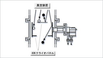
Launch of Cryogenic trap using a helium refrigerator to replace CFC substitute cold trap
-
Rapid low-temperature regeneration ... Reduction of regeneration time.
-
Applications and examples of effective use of Super Traps
-
Liquid Nitrogen Generator in diverse fields
-
Vacuum Gauge ST2 Technical report
-

Liquid Nitrogen Generators | Technical Report
-
Development of a quartz crystal disc with a resonance frequency of 4 MHz
-

HELIOT900 | Technical report
-
Cryogen Free Dilution Refrigerator using 4K-Cryocooler
Solution
- Big Science
- Lifestyle
- Technology
- Medical Field